in the meantime, are you able to send data between 2 nodes using tests/driver_sx127x? If that doesn’t work, then confirms what I wrote above
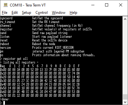
even better, you should be able to get the registers with the “register” command (I think it was “register all”). If you see only zeros, then it confirms there’s something wrong with the pinout
Well, i will wait you tests on NRF52… Thanks
I’m running the tests now. But from what I see, the SPI line seems to be connected properly. The register 0x42 (SX127X_REG_LR_VERSION) is 0x12, which maps to VERSION_SX1276. So, I guess that’s right.
Even if you didn’t connect the DIO pins properly, you should still be able to see packets in the Network Sever. Are you 100% sure the keys are right?
well, it works for me… This is the pin configuration I’m using:
diff --git a/drivers/sx127x/include/sx127x_params.h b/drivers/sx127x/include/sx127x_params.h
index 661c37e80c..30e4ace4b7 100644
--- a/drivers/sx127x/include/sx127x_params.h
+++ b/drivers/sx127x/include/sx127x_params.h
@@ -37,19 +37,19 @@ extern "C" {
 #endif

 #ifndef SX127X_PARAM_SPI_NSS
-#define SX127X_PARAM_SPI_NSS                GPIO_PIN(1, 6)       /* D10 */
+#define SX127X_PARAM_SPI_NSS                GPIO_PIN(1, 12)       /* D10 */
 #endif

 #ifndef SX127X_PARAM_RESET
-#define SX127X_PARAM_RESET                  GPIO_PIN(0, 0)       /* A0 */
+#define SX127X_PARAM_RESET                  GPIO_PIN(0, 3)       /* A0 */
 #endif

 #ifndef SX127X_PARAM_DIO0
-#define SX127X_PARAM_DIO0                   GPIO_PIN(0, 10)      /* D2 */
+#define SX127X_PARAM_DIO0                   GPIO_PIN(1, 3)      /* D2 */
 #endif

 #ifndef SX127X_PARAM_DIO1
-#define SX127X_PARAM_DIO1                   GPIO_PIN(1, 3)       /* D3 */
+#define SX127X_PARAM_DIO1                   GPIO_PIN(1, 4)       /* D3 */
 #endif

 #ifndef SX127X_PARAM_DIO2
@@ -57,7 +57,7 @@ extern "C" {
 #endif

 #ifndef SX127X_PARAM_DIO3
-#define SX127X_PARAM_DIO3                   GPIO_PIN(1, 4)       /* D5 */
+#define SX127X_PARAM_DIO3                   GPIO_PIN(1, 6)       /* D5 */
 #endif

 #ifndef SX127X_PARAM_PASELECT
(using sx1276 and nrf52840dk).
Then this is the tests/driver_sx127x session between 2 nodes (including timestamps so you can see in which order the commands were called)
Node 1:
> 2021-02-03 14:07:48,123 #  main(): This is RIOT! (Version: 2021.04-devel-353-g13b97)
2021-02-03 14:07:48,158 # Initialization successful - starting the shell now
setup 125 7 5
2021-02-03 14:07:51,145 #  setup 125 7 5
2021-02-03 14:07:51,148 # setup: setting 125KHz bandwidth
2021-02-03 14:07:51,153 # [Info] setup: configuration set with success
channel set 868000000
2021-02-03 14:07:57,082 #  channel set 868000000
2021-02-03 14:07:57,083 # New channel set
send "Hello from node 1"
2021-02-03 14:08:21,213 #  send "Hello from node 1"
2021-02-03 14:08:21,217 # sending "Hello from node 1" payload (18 bytes)
> 2021-02-03 14:08:21,273 #  Transmission completed
listen
2021-02-03 14:08:27,530 # listen
2021-02-03 14:08:27,532 # Listen mode set
> 2021-02-03 14:08:31,897 #  Data reception started
2021-02-03 14:08:31,932 # {Payload: "Hello from node 2" (18 bytes), RSSI: 131, SNR: -6, TOA: 57}
Node 2
2021-02-03 14:07:23,019 # main(): This is RIOT! (Version: 2021.04-devel-353-g13b97)
2021-02-03 14:07:23,053 # Initialization successful - starting the shell now
> setup 125 7 5
2021-02-03 14:07:34,565 #  setup 125 7 5
2021-02-03 14:07:34,569 # setup: setting 125KHz bandwidth
2021-02-03 14:07:34,573 # [Info] setup: configuration set with success
> 2021-02-03 14:07:49,031 #  main(): This is RIOT! (Version: 2021.04-devel-353-g13b97)
2021-02-03 14:07:49,065 # Initialization successful - starting the shell now
> setup 125 7 5
2021-02-03 14:07:54,121 #  setup 125 7 5
2021-02-03 14:07:54,123 # setup: setting 125KHz bandwidth
2021-02-03 14:07:54,127 # [Info] setup: configuration set with success
channel set 868000000
2021-02-03 14:08:01,598 #  channel set 868000000
2021-02-03 14:08:01,600 # New channel set
> listen
2021-02-03 14:08:11,768 #  listen
2021-02-03 14:08:11,770 # Listen mode set
> 2021-02-03 14:08:21,243 #  Data reception started
2021-02-03 14:08:21,279 # {Payload: "Hello from node 1" (18 bytes), RSSI: 131, SNR: -5, TOA: 57}
send "Hello from node 2"
2021-02-03 14:08:31,868 # send "Hello from node 2"
2021-02-03 14:08:31,873 # sending "Hello from node 2" payload (18 bytes)
> 2021-02-03 14:08:31,927 #  Transmission completed
I even configured the DIO wrong and confirmed the node was sending (althogh it won’t receive in this case).
Does this work for you? (you should use 915000000 instead of 868000000 when using the channel set command).
I really really dont have luck!
Now with this example my CDC USB SERIAL not works  I will be back on these tests late!
thanks for all the help!
I will be back on these tests late!
thanks for all the help!
got some progress! Sent a message using APB MODE to my LORAWAN gateway!
Tryng to find out how to make the JOIN works !
1 Like
Did you use confirmed uplinks ? If yes you should be able to use OTAA as well ( we can then rule out issues with HW wiring ). Regarding OTAA are you able to see the OTAA join requests in console ?
Hello @akshaim
How are you ?
Using APB i can confirm the UPLINKS and works
About the OTAA, no UPLINKS, why i got JOIN fail
Hey, I meant “CONFIRMED” Uplinks.